Lucid Modifier
- Lucid Modifier
- MaxScript access
Overview
Lucid Modifier is an Object Space Modifier which can be applied to most geometry in 3dsmax such as meshes and splines to make them a part of Lucid simulation. This modifier contains general object-specific parameters such as density and material type as well as material-specific parameters such as cloth stiffness or fluid meshing.
Inline help
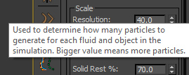
If you hover over most of these parameters a tool-tip will appear giving you more information about that particular parameter. This is a great way to learn more about each Lucid setting on the spot.
Adding Lucid Modifier
There are a number of ways of adding Lucid OSM to a scene object:- Select your object and use Modifier Panel to browse the list of modifiers. Select Lucid Modifier from the list.
- Use the Lucid Toolbar preset drop-down to select a preset while your object is selected.
Particle meshing
Particle meshing is done using a glorified "marching ant" algorithm which walks the volume of the particles and generates a polygon mesh based on whether it falls inside a particle or outside of it. To do this the particle volume is broken down into a 3-dimensional grid consisting of many voxels. The size of individual voxels determines their overall count and the detail of the resulting mesh. A parameter called Granularity specifies this size. Granularity has no effect on simulation itself and only affects particle meshing. If you want to increase the resolution or number of particles in simulation you need to use the Resolution or Manual Radius parameters in global Flex Settings.
Additional effects can be applied to meshing such as generating water droplet shapes through motion paths and smoothing of particles using OpenVDB filters.
Parameters
Preset
Provides a list of predefined settings for the modifier which will simulate various materials for your object. Once you select a preset it will change the modifier's parameters to make it behave like the selected material. For example, you can select a Wood or a Water preset.
Body Type
Specifies the physical type (material) of the current object. Each body type will make the object behave differently during the simulation. These are the options available:
- Rigid - Used to simulate hard surfaces like stone, metal, and wood. The object will be simulated as solid collection of particles connected with rigid springs.
- Fluid - Used to simulate liquids like water, glue, and mud. The object will be simulated as a volume of fluid. The viscosity and other settings can be set to modify the fluid behavior.
- Soft - Used to simulate bouncy, squishy, and otherwise soft objects like rubber, pillows, and jelly. Similarly to Rigid body type, object will be simulated using a lattice of particles. However, the springs between the particles will be soft.
- Cloth - Used to simulate fabric. Surface of the mesh will be simulated using a lattice of particles. Special behavior like tearing can be specified.
- Inflated - Used to simulate filled objects like balloons, tires, and bubbles. Behaves similar to cloth, but has a volume.
- Collision - Used to specify unmovable objects like terrain and walls. Any mesh can be used robustly with this body type as long as it doesn't move during simulation.
- Convex - Similar to Collision body type, used to simulate animated, but non-deforming objects like animated bars, walls, and stones. If geometry is not convex it will be segmented into a collection of convex meshes automatically.
- SDF - Similar to Collision and Convex body types, used to simulate animated and deforming objects like a character's body. This is the only collision body type that can be deforming during the simulation at the expense of slower performance.
Depending on the body type you select you will be presented with different parameter rollouts in the modifier.
The body type parameter can be animated over time to change the type of simulation performed on the object. For example, you can start simulating the object as a fluid, let it spill in the scene, and then simulate the object as a soft-body for the rest of the time. It is important to note that you must set the key interpolation type in 3dsmax to Step to avoid interpolating this parameter between time frames.
|
Changing body type tutorial |
Enabled
When this option is on the object with current modifier will participate in the simulation, otherwise it will be ignored. This is useful for temporarily removing some objects from the simulation.
Time Range
If you don't want an object to be inside the simulation for the whole simulated range you can use these options to specify the start and end frames of the range where the object will be added and removed to/from the simulation.
Use Time Range
|
Object time range tutorial |
Toggles whether object will use the custom time range or be present for the whole duration of the simulation.
Start Time
First frame where object is added into simulation
End Time
Last frame where object is removed from simulation
Common
Common properties which apply to all body types.
Set/Clear Initial State
This button will be enabled during simulation. It allows you to specify the state of the object which will be used to start a simulation. For example, you can create a fluid volume and then simulate it in real-time until it settles into a pool. Then you can capture this state so that next time the simulation starts it will already have the shape of the pool.
|
Set initial state tutorial |
If initial state was previously set you can click this button again to clear the state. The object initial state is stored with the scene and as such will increase the scene size when present.
Preserve Initial Velocity
When on, velocity of object's vertices will be calculated from key-framed animation inside the scene right before it begins simulating. This velocity will be passed on to the simulated object at the start of the simulation.
|
Preserve initial velocity demonstration (Begin at 3:00) |
Density
Specifies how dense the object's particles will be. This indirectly sets the mass of the object. The bigger the density the heavier the object will appear during simulation. You can mix multiple fluids with different densities to create various non-uniform fluid effects. Likewise you can make objects buoyant or sinkable in fluid by making them heavier or lighter than the fluid object.
Rigid
Controls rigid body settings
Stiffness
Sets the rigidity of connections between particles in rigid body objects.
Spacing
Sets how far apart lattice particles are generated from one another in rigid body objects.
Display
Show as Particles
Specifies whether to display the object as particles or mesh. Read more on particle display.
Geometry Changes
Use Soft Selection
If this option is on and body type is inflated or cloth then vertex soft selection of incoming mesh will be used to blend the simulated object shape with the incoming object shape. This is useful if, for example, simulating a piece of cloth on a character's body to keep part of the cloth animation while allowing other parts to be simulated.
Cloth and Inflated Parameters
Settings
Self-collisions
If on, the particles in current objects will be allowed to collide with one another. This should be on if you want a piece of cloth to interact with itself, for example, if simulating a flag.
Stretch
Controls how much cloth particles are allowed to move away from one another. Makes cloth more rubbery when increased.
Bend
Controls how much the cloth is allowed to bend.
Tearing
|
Cloth tearing tutorial |
Tearing
Specifies the magnitude of the force between cloth particles required to break their connection. If this value is 0 then tearing will never happen.
Random Seed
Controls the random variation of cloth tearing
Cloth tearing map
If map is assigned to this parameter then it will act as a multiplier to the Tearing parameter to control the joint tearing forces. White values of the map will be more tearable than the black values.
Recording Settings
Used to control if and how the object simulation is recorded.
Record Data
When on, the object simulation will be recorded during recording.
Clear Recording
If recorded data is present pressing this button will clear it, otherwise the button is disabled.
Save to File
If checked the recorded data will be saved to an external file instead of being embedded in the scene. See recording simulation documentation for more information.
|
Caching to external .lrd and .prt files |
Fluid Settings
If body type is set to Fluid you will see these settings.
Meshing Options
Controls meshing of the fluid if not displaying as particles.
Fluid Constraints
If this option is on then particles will act as a fluid. Otherwise, the particles will not stick to each other. Turn this off to simulate sand and grains.
Particle Occlusion Map
A 2d or 3d texture map can be specified here to avoid generating particles in certain places of the mesh volume. World coordinates inside the mesh are passed into the map.
|
Particle occlusion maps tutorial |
Granularity
Specifies the detail of the fluid mesh. Smaller value will make the resulting mesh more dense and accurate at the expense of computation speed. It is generally a good idea to set a larger value during preview and then decrease the value when rendering.
Mesh Type
Specifies the type of information carries by the particles. Having additional direction information can help produce better fluid meshes.
- Isotropic: Fluid particles will contain directional information from particles
- Anisotropic: Fluid particles will not contain any extra directional information
|
Anisotropic particles overview (Begin at 3:45) |
Scale Particles
Allows to manually increase or decrease the isotropy information carries with particles.
Texture Coordinates
Lucid can preserve the texture coordinates of the fluid volume mesh. The resulting meshed fluid will have the coordinates at each vertex closely matching the coordinate of particles that were generated from the original mesh. This does have a slight overhead in terms of computing performance.
|
Fluid mesh texture coordinates |
Generation
- None: Texture coordinates will not be generated
- World Coordinates: Texture coordinates will be generates based on the fluid particle world positions. Useful if you want to have texture coordinates but if source mesh doesn't provide them. This also allows particles within the volume to have 3-dimensional texture coordinates.
- Inherit from Mesh: Texture coordinates will be inferred from the fluid volume mesh.
Near Particles
Specifies the number of particles to use per each result mesh vertex to sample the result UVW texture coordinate. Can be used to smooth the texture coordinates in the resulting mesh.
Near Vertices
Specifies the number of vertices of fluid volume mesh to use for each particle to sample the UVW coordinate for that particle. Used to reduce UVW artifacts when generating particles.
Softbody Settings
These parameters control the way that soft lattice particles are generated from a mesh with soft body type.
|
Soft body parameter tweaking (Begin at 4:22) |
Adopt Mesh Animation
When on, the deformations from the mesh will be passed into the Lucid simulation. Useful for simulating objects which generate their own locomotion from movement like snakes and worms.
|
Simulating deforming soft body objects |
Convex Settings
Controls how convex collision meshes are generates from source geometry.
Convex Segmentation
If the source object is not itself convex Lucid can automatically generate a set of convex sub-objects from it through segmentation.
|
Convex mesh segmentation (Begin at 6:45) |
- None: No segmentation happens, source object will be used as-is. If it isn't convex then it will not participate in the simulation. No extra processing is done.
- Convex Hull: If source object is not convex a single convex hull will be constructed from it. Good way to ensure that the object will for sure be present in the simulation, however, it might not produce correct or precise results if it is concave.
- Quick Segmentation: If the source object is not convex a segmentation algorithm will split it into sub-objects which are convex. The resulting set of objects will try to match the original geometry as closely as possible.
- Accurate Segmentation: Same as Quick Segmentation but more care is given to segmentation to produce more detailed results at the expense of computing speed.
Signed Distance Field Settings
These settings appear when SDF is used for object's body type.
|
Deforming collision objects (Begin at 4:30) |
Is Dynamic
Turn this option on if your collision mesh is deforming over time. When it is on, this option will update the collision mesh inside Lucid at each frame sub-step. This will make the simulation slower, however.
Resolution
Determines the detail at which Lucid will render the signed distance field used to represent the collision object internally. The higher this value then more accurate collisions you will get, at the expense of the computing speed.
Curve Settings
These properties appear when you apply Lucid modifier to a spline and NURBS curve object.
|
Creating simple ropes (Begin at 2:50) |
Curve simulation parameters (Begin at 3:40) |
General
Input Samples
Determines how many points to sample on the incoming curve. For example, if this parameter is 2 only the root and tip of the curve are sampled. More samples mean more detail will be sampled from the curve and more particles will be generated from it.
Smoothing
Used to normalize the sampled points to produce a smooth curve.
Slice Particles
Specifies the number of particles to have in the cross-section of the curve. For example, a value of 1 will create a simple chain of particles going along the curve. A value of 2 will create a ribbon, and a value of 3 will create a prismatic mesh around the curve. Larger values of this parameter will ensure that the curve is less bendy and more rigid.
Spacing
Adds an offset between sampled particles along the curve length.
Radial Spacing
Determines the size of the curve cross-section. Larger value will make simulated curve lattice thicker and thus less flexible.
Rotation Along
Allows to add a twist of cross-sections in particle lattice along the curve length.
Spring Constraints
Spring Stiffness
Controls how loose or stiff the simulated curve is.
Rigid Constraints
These values define the constrains on the joints used to connect the simulated curve particles together into a lattice.
Rigid Stiffness
If 0, rigid constraints will be disabled. Otherwise, sets the rigidity of the constraints.
Rigid Slice Count
Determines the number of slices used for rigid constraints.
Rigid Overlap
This value needs to be smaller than Rigid Slice Count. It determines how many particles will be shared between each cross-section of the simulated particle lattice.
MaxScript access
Lucid modifier parameters can be accessed via standard MaxScript commands. Use showProperties function to get a list of modifiable properties.
Sample code for dealing with Lucid modifiers: Test_ObjectSpaceModifier.ms